PLCopen 2-Axes Template with FFLD
This template project contains a two-axis template for getting started with a KAS application. It contains key project elements that will save development time. Additional axes can be added to the template applications that have three, four, five, or more axes. The templates are designed to easily add code to the programs and Control Panels that are in the template or to new ones. A project can contain many programs, and each program can be written in ST![]() "Structured text"
A high-level language that is block structured and syntactically resembles Pascal, SFC
"Structured text"
A high-level language that is block structured and syntactically resembles Pascal, SFC![]() "Sequential function chart"
It can be used to program processes that can be split into steps.
The main components of SFC are:
- Steps with associated actions
- Transitions with associated logic conditions
- Directed links between steps and transitions, FFLD, FBD
"Sequential function chart"
It can be used to program processes that can be split into steps.
The main components of SFC are:
- Steps with associated actions
- Transitions with associated logic conditions
- Directed links between steps and transitions, FFLD, FBD![]() "Function block diagram"
A function block diagram describes a function between input variables and output variables. A function is described as a set of elementary blocks, or IL
"Function block diagram"
A function block diagram describes a function between input variables and output variables. A function is described as a set of elementary blocks, or IL![]() "Instruction list"
This is a low-level language and resembles assembly programming languages. This template program can be run on the KAS Simulator or with a AKD PDMM or PCMM and AKD drives.
"Instruction list"
This is a low-level language and resembles assembly programming languages. This template program can be run on the KAS Simulator or with a AKD PDMM or PCMM and AKD drives.
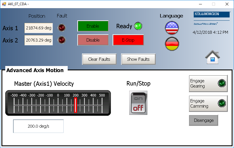
This project contains two axes where Axis 2 is slaved to Axis 1 at a 2:1 ratio.
PLC Programs
The 2-axes PLCopen![]() A vendor -and product- independent worldwide association active in Industrial Control and aiming at standardizing PLC file formats based on XML template has a FFLD program (called Main) that initializes and starts the motion. The motion includes single axis jogging, incremental and absolute moves, and gearing motion between axes. Also included are controls to enable/disable the drives, clear faults, and display fault and axis position information in the Control Panel.
A vendor -and product- independent worldwide association active in Industrial Control and aiming at standardizing PLC file formats based on XML template has a FFLD program (called Main) that initializes and starts the motion. The motion includes single axis jogging, incremental and absolute moves, and gearing motion between axes. Also included are controls to enable/disable the drives, clear faults, and display fault and axis position information in the Control Panel.
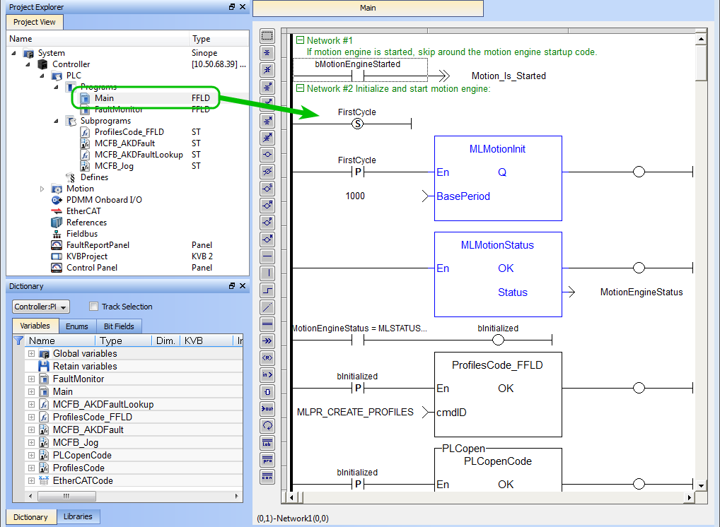
Figure 7-55: PLCopen Template with FFLD - Main
Motion
The template contains two PLCopen Servo axes where User Units, Update Rate, Rollover Position, and Axis Limits are defined as follows:
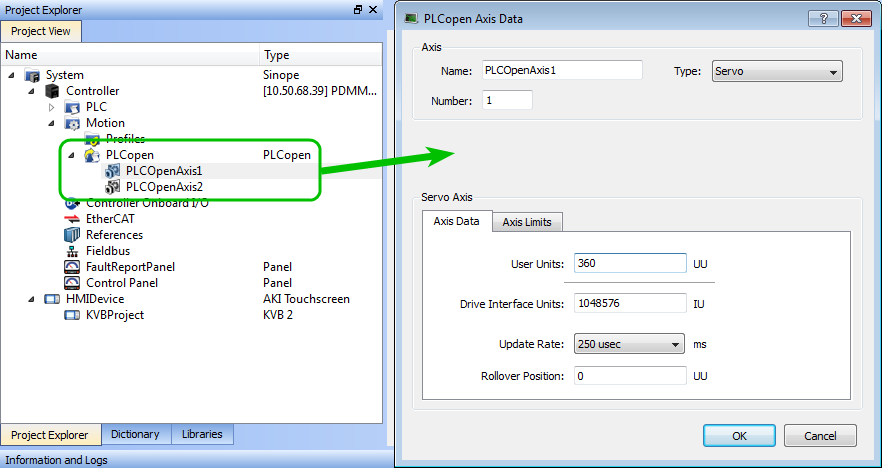
Figure 7-56: PLCopen Template - Motion
For more details on PLcopen axis parameters, see "Axis Data Parameters"
Control Panel
The template contains a Control Panel which works inside of the IDE![]() "Integrated development environment"
An integrated development environment is a type of computer software that assists computer programmers in developing software.
IDEs normally consist of a source code editor, a compiler and/or interpreter, build-automation tools, and a debugger when running a project, and serves as a useful tool to run and debug programs. The Control Panel consists of two screens, named Control Panel and Fault Report Panel.
"Integrated development environment"
An integrated development environment is a type of computer software that assists computer programmers in developing software.
IDEs normally consist of a source code editor, a compiler and/or interpreter, build-automation tools, and a debugger when running a project, and serves as a useful tool to run and debug programs. The Control Panel consists of two screens, named Control Panel and Fault Report Panel.
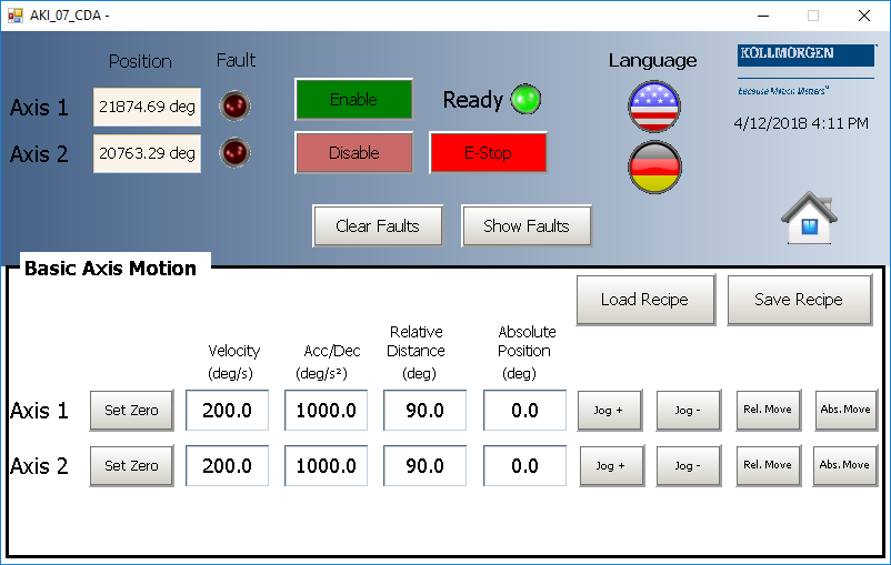
Control Panel consists of three sections.
- Multi-Axis Commands which controls motion and shows gearing
- Single Axis Motion Commands which shows motion at the single axis level and resetting the axis position
- Axis Status which shows basic axis information
For more details, see Design the Control Panel with the Internal Control Panel Editor
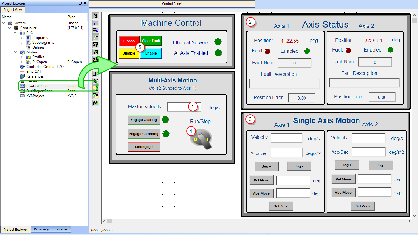
Figure 7-57: PLCopen Template - Control Panel
| Call out# | Description |
|---|---|

|
Allows you to set the speed |

|
Displays the actual position for each axis |

|
Control the axis motion |

|
Start or stop the motion on the condition that the axes are enable (the green light must be switched on) |

|
Allows for enabling or disabling the axes. After an emergency stop, you need to select the Reset and Enable commands before running the axes |
Table 7-40: PLCopen Template - Control Panel elements
Fault Report Panel provides more detailed information about when a drive fault occurs.
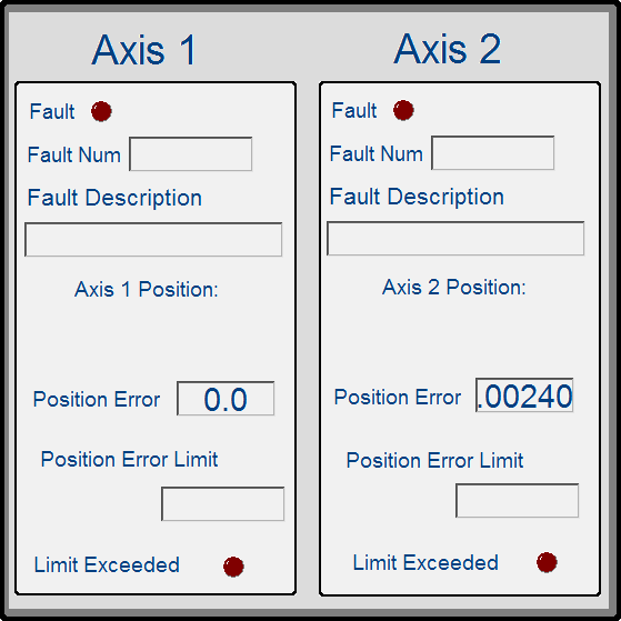
Figure 7-58: PLCopen Template - Fault Report Panel
Based on the template, the project can be run:
- using the KAS Simulator
- with actual drives and motors (in this case, you first have to set up the axes in the EtherCAT
 ***EtherCAT is an open, high-performance Ethernet-based fieldbus system. The development goal of EtherCAT was to apply Ethernet to automation applications which require short data update times (also called cycle times) with low communication jitter (for synchronization purposes) and low hardware costs part. For more details, see "Configuring EtherCAT")
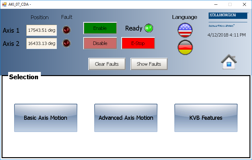
HMI
Also included in the project template are HMI![]() "Human-machine interfaces "
Also known as computer-human interfaces (CHI), and formerly known as man-machine interfaces, they are usually employed to communicate with PLCs and other computers, such as entering and monitoring temperatures or pressures for further automated control or emergency response screens for the AKI terminals created in the KVB (Kollmorgen Visualization Builder) environment.
"Human-machine interfaces "
Also known as computer-human interfaces (CHI), and formerly known as man-machine interfaces, they are usually employed to communicate with PLCs and other computers, such as entering and monitoring temperatures or pressures for further automated control or emergency response screens for the AKI terminals created in the KVB (Kollmorgen Visualization Builder) environment.
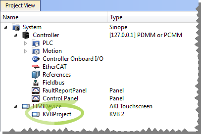
The KVB software is a separate installation from the KAS IDE. KVB can be opened from within KAS IDE by double-clicking on the KVBProject item in the project tree.
The project can be run in the KVB programming environment after the KAS IDE program has started running. Click on the Run button in the Project ribbon to start the program.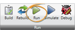
Four screens, localized in English and German, are included that duplicate the controls on the IDE Internal Control panel screens.